
Voltage Divider Calculator
Here
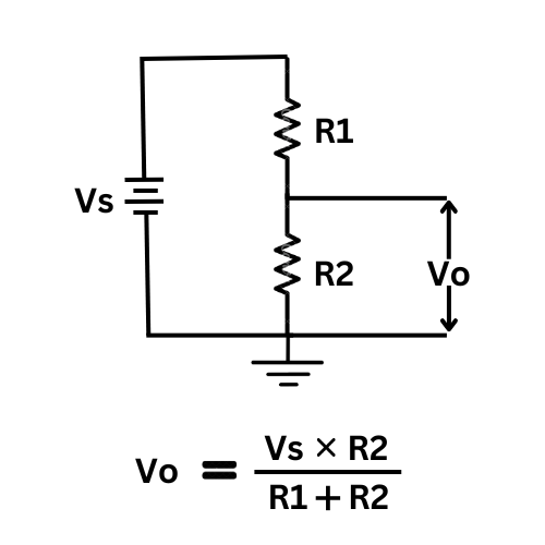
- Vs = Source voltage in Volt
- R1 = Resistor labeled R1 in the image
- R2 = Resistor labeled R2 in the image
- Vo = Voltage across R2 in Volt
Understanding the Voltage Divider Rule: Theory, Applications, and Practical Examples
The voltage divider rule is one of the fundamental principles in electronics. Whether you’re a hobbyist building your first circuit or a seasoned engineer designing complex systems, understanding this rule can help you manipulate and control voltage levels with precision. In this article, we’ll dive deep into the voltage divider concept, explain its underlying theory, and explore practical applications that make it an essential tool in modern electronics.
What Is the Voltage Divider Rule?
At its core, the voltage divider rule describes how the voltage supplied to a series of resistors is divided among them. In a simple series circuit, when resistors are connected end-to-end, the input voltage (often called VinV_{in}Vin) is apportioned between each resistor in direct proportion to its resistance. For example, in a two-resistor divider circuit, the voltage across one resistor can be calculated using the formula:
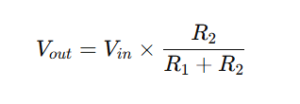
Here, R1R_1R1 and R2R_2R2 are the resistances in the series, and VoutV_{out}Vout is the voltage across R2R_2R2. This simple equation helps engineers and enthusiasts determine how much voltage is dropped across each resistor, making it easier to design circuits that require precise voltage levels.
How the Voltage Divider Works
To understand the voltage divider rule, imagine a single loop circuit powered by a battery. When two resistors are connected in series, the same current flows through both. The battery’s voltage is “divided” between the resistors according to their values. The larger the resistance, the greater the voltage drop across it.
Breaking Down the Circuit
- Series Connection: In a series circuit, resistors are connected one after the other, so the same current flows through each resistor.
- Ohm’s Law: This rule relies on Ohm’s law, which states V=I×RV = I \times RV=I×R (voltage equals current times resistance). Since the current is the same across resistors in series, the voltage drop across each resistor is directly proportional to its resistance.
- Proportional Division: The sum of the voltage drops across the resistors equals the total input voltage. Thus, if you know the resistances, you can calculate the voltage drop across any resistor in the series.
A Practical Example
Consider a circuit where VinV_{in}Vin is 12 volts, R1R_1R1 is 2 kΩ, and R2R_2R2 is 3 kΩ. Using the voltage divider formula:
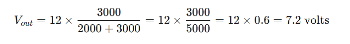
This means that 7.2 volts will appear across the 3 kΩ resistor. By understanding this distribution, you can design circuits that deliver the appropriate voltage to each component.
Applications of the Voltage Divider Rule
The voltage divider is ubiquitous in the world of electronics because of its versatility and simplicity. Here are some of the most common applications:
1. Sensor Interfacing
Many sensors require specific voltage levels to operate correctly. For instance, when working with temperature sensors or light-dependent resistors (LDRs), the voltage divider can be used to create a reference voltage or to convert a variable resistance into a measurable voltage. This is especially useful when interfacing with microcontrollers like Arduino or Raspberry Pi, where analog-to-digital converters (ADCs) need a stable voltage range.
2. Biasing Transistors
In amplifier circuits, transistors need to be biased correctly to operate in their optimal range. The voltage divider is often used to set the base voltage of a transistor, ensuring that the transistor remains in the active region and functions properly as an amplifier.
3. Level Shifting
Modern electronic circuits sometimes need to interface components that operate at different voltage levels. A voltage divider can be used as a simple level shifter, adapting the voltage from one part of a circuit to match the requirements of another without the need for more complex circuitry.
4. Signal Conditioning
In audio and other analog signal circuits, voltage dividers help in attenuating signals. This process is crucial for ensuring that signals are within a range that can be safely processed by other circuit components, such as amplifiers or digital converters.
Design Considerations and Limitations
While the voltage divider rule is straightforward and highly useful, there are several design considerations to keep in mind:
Load Effects
One of the most common pitfalls in using voltage dividers is not accounting for the load connected to the divider’s output. When a load (another circuit component) is connected, it effectively becomes part of the divider, altering the expected voltage. To minimize this effect, the divider’s output should have a much lower impedance compared to the load, or alternatively, a buffer amplifier can be used.
Power Consumption
Voltage dividers continuously draw current from the power supply, which can lead to unnecessary power consumption, especially in battery-powered devices. It’s important to design voltage dividers with appropriate resistor values that minimize current draw while still providing accurate voltage levels.
Accuracy and Tolerance
The resistors used in the divider have tolerance ratings, meaning their actual resistance can vary from the nominal value. In precision applications, this variation can lead to errors in the output voltage. Using precision resistors or calibrating the circuit can help mitigate these issues.
Temperature Dependence
Resistor values can change with temperature, impacting the voltage divider’s performance. This is particularly important in environments where temperature variations are significant. Selecting resistors with low temperature coefficients can help maintain consistent performance.
Practical Tips for Using Voltage Dividers
If you’re designing circuits with voltage dividers, consider the following best practices:
- Calculate Expected Load: Always determine the impact of any connected load on your voltage divider and design accordingly.
- Use Precision Resistors: In applications where accuracy is critical, invest in high-precision resistors.
- Consider Power Budget: Optimize resistor values to balance the need for accurate voltage division with power consumption requirements.
- Simulate Before Implementation: Use circuit simulation tools to test your voltage divider under different conditions. Many online calculators and simulation software can help you predict how your circuit will perform before you build it.
- Buffer When Necessary: For applications where the voltage divider’s output is heavily loaded, consider adding a buffer amplifier to maintain voltage levels.
Integrating Voltage Divider Calculators into Your Workflow
With the rise of digital tools, many engineers and enthusiasts now rely on voltage divider calculators to streamline their design process. These calculators allow you to quickly input values and see how different resistor combinations affect the output voltage. By automating the calculation process, you can experiment with various configurations and find the optimal design for your application.
Benefits of Using a Voltage Divider Calculator
- Time Efficiency: Rather than manually calculating each potential configuration, a calculator provides instant feedback.
- Accuracy: Automated tools reduce the risk of human error in arithmetic calculations.
- Educational Value: For students and beginners, these calculators can serve as a learning tool, helping them understand the relationship between resistor values and voltage distribution.
- Design Optimization: When integrated into simulation software, voltage divider calculators can help optimize circuit designs for performance, cost, and power consumption.
Real-World Examples and Advanced Applications
Beyond the basic applications discussed above, voltage dividers are also used in more advanced circuits. For instance, in analog-to-digital conversion circuits, voltage dividers help to condition input signals so they fall within the optimal range of the converter. In radio frequency (RF) circuits, attenuator networks based on the voltage divider concept help control signal amplitudes and prevent overloading of sensitive components.
Case Study: Sensor Calibration
Consider a scenario where an engineer needs to calibrate a sensor that outputs a voltage proportional to the measured parameter. By designing a voltage divider, the engineer can scale down the sensor output to match the input range of a microcontroller’s ADC. This ensures that the sensor’s readings are both accurate and within a safe operating range, leading to better performance and reliability in the final product.
Innovations in Circuit Design
Recent advances in electronics have also seen the integration of digital potentiometers into voltage divider circuits. This allows for dynamic adjustments of resistance values, making it possible to automatically calibrate and adjust the output voltage in real time. Such innovations pave the way for more adaptable and intelligent systems in fields ranging from consumer electronics to industrial automation.
Conclusion
The voltage divider rule is much more than a simple formula—it is a versatile tool that forms the backbone of many electronic circuits. Whether you’re designing sensor interfaces, biasing transistors, or simply need to shift voltage levels, the principles behind the voltage divider are both elegant and indispensable.
By understanding how voltage divides in a series circuit and accounting for practical considerations like load effects and resistor tolerances, you can design more reliable and efficient circuits. Embracing tools such as voltage divider calculators further enhances your ability to experiment and innovate, ensuring that your designs are both precise and adaptable to a range of applications.
In a world where electronic devices are becoming increasingly complex, the ability to control and manipulate voltage levels with ease is a skill that every engineer and hobbyist should master. With the voltage divider rule, you have a powerful ally in your design toolkit—one that combines simplicity with functionality to help bring your electronic projects to life.
By following these guidelines and exploring the many applications of the voltage divider rule, you can unlock new levels of creativity and precision in your circuit designs. Happy designing!
[…] Calculate Now Calculate Now Calculate Now […]